Exploring possible human knowledge


Paul Vjecsner

PRESUMED IMPOSSIBILITIES

(18 November 2004. To the reader: This page has become the most visited one on this website, and I therefore feel I should call to the attention of the visitor that I treat other what may be viewed as thought-provoking subjects in the book mentioned on the home page. On that page I now added at the start a parenthesized paragraph like the present one, giving more information about the contents of the book. Perhaps the visitor of this page will find those contents likewise stimulating.)

(16 January 2006. After further consideration of the present issues, I thought I should bring out some matters I see as quite important. These pages are mainly confined to what I see as falsely presumed impossibilities. However, I also find many other false conclusions reached in highly respected fields, as I explore them in my book. What can be especially startling is that these falsehoods abound particularly in mathematics, a science considered most exact. What is more, the mathematical community fails to recognize a single thing wrong in the field. Physical sciences at least admit, if reluctantly, that its accepted views are revisable theories, but in mathematics the closest thing to this uncertainty appear to be what are known as conjectures. Writing more fully on this, as indicated, elsewhere, I feel compelled to at least mention here areas containing the falsities. Here noted ones are in non-Euclidean geometry, which consistently redefines terms to so commit the fallacy of equivocation; others concern set theory [a fitting name perhaps], regarding which infinite magnitudes are contradictorily considered and paradoxes wrongly interpreted; and still others are arbitrary postulates on which reasoning is built. The questioning of this and more is expectably resented, but it should instead be looked at with at least somewhat open minds.)

In the past—going back often to antiquity—thinkers have tackled many problems pronounced more recently as insoluble. Most have occurred in mathematics, and especially in geometry, owing to its renowned Greek legacy. It is my sense that the continued futility in solving the problems, and the eagerness to prove one's mettle, led many to prematurely decide that, rather than finding the answer sought, they found it to be impossible. Maybe the most famous of these problems is a proof of what is known as Euclid's 5th, or the parallel, postulate. My own consideration of it is included in the book referred to on the home page, so I will not consider it directly at present. But I might note, shocking as the idea is today, that I find the claim of that postulate's unprovability false and, yet more shocking, offer a proof.

At this time I would like to turn to some other ancient problems in geometry. A well known threesome of them is the trisection of an arbitrary angle, the duplication of the cube, and the squaring of the circle. Related is the construction of a regular heptagon. These are of interest to me at this moment because I just recently wrote about some to Professor Robin Hartshorne of the University of California at Berkeley, whose book, Geometry: Euclid and Beyond, I previously obtained.

At issue in the above mentioned constructions is performing them by use of merely compass and unmarked ruler, in the Euclidean tradition. They were only found instead possible by using added devices such as marks on the ruler, and also involving a "sliding" or "insertion" to make the tool fit certain points and lines, rather than depending on points determined. Whatever action was used, however, the constructions were never accomplished by compass and unmarked ruler alone.

This is here my main interest, without considering any proof presented that the constructions are in some manner impossible. With regard to only the past inability of using compass and unmarked ruler alone however applied, I indeed found ways of using these tools for such purposes. In my letter to Professor Hartshorne I turned specifically to the trisection and the heptagon, which he dealt with in detail in his book and are treated in the below drawings I sent him.

HOME

PRESUMED IMPOSSIBILITIES, continued1, 2

PHOTOGRAPHY, continued1, 2, 3, 4

PORTRAITURE, continued1, 2, 3

COMMERCIAL ART, continued1, 2, 3, 4, 5, 6, 7, 8, 9, 10, 11, 12, 13, 14, 15, 16, 17, 18, 19, 20, 21, 22, 23, 24, 25

INVENTION

AUTOBIOGRAPHY, continued1, 2, 3, 4

Both of them concern what was previously an insertion of a line by means of a marked ruler. The first drawing is of a simplified trisection that can correspondingly not be constructed with such a ruler, which relies on a length already given. The second drawing will serve to illustrate this reliance.

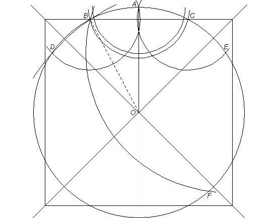
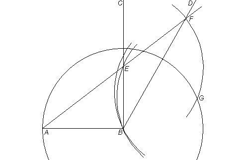
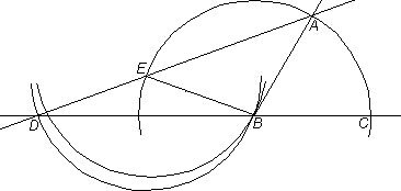
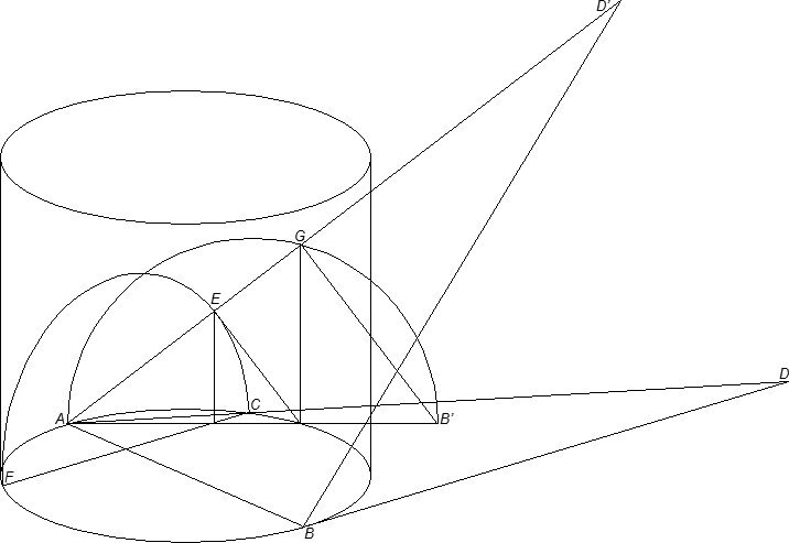
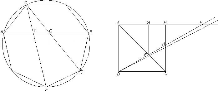
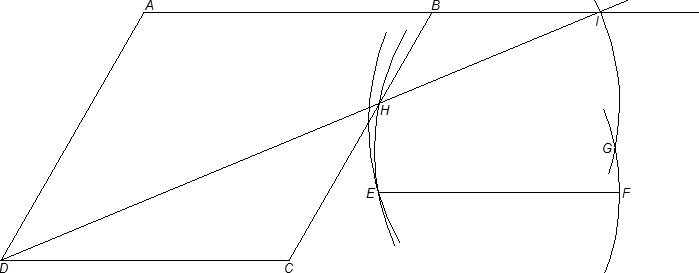
It is about a heptagon construction shown on page 265 of the book by Professor Hartshorne. In it the distance CF is marked on a ruler by which that distance is then transferred to segment GH by "sliding" the ruler so that the mark for G falls on arc CG and the mark for H falls on line HF while line HGC goes through C. What was not recognized is that the same is accomplished if a compass with a center G on arc GC is positioned to describe an arc from F to a point H lying on lines HF and HGC which goes through C. In this drawing an unmarked ruler pivots on C till H is on the horizontal. (To briefly describe what in the construction is done before, with the right-side intersection of the circle and its extended horizontal diameter as center, and the radius of the circle, an arc is marked on the circle at C and the point vertically below it; with the distance between these two points as radius, and the same center as of the circle, the bottom arc on the vertical is marked; from that point the line to C is drawn, and with its intersection F on the horizontal as center the arc CG is described.)

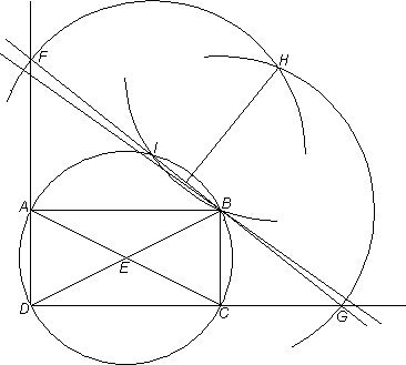
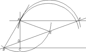
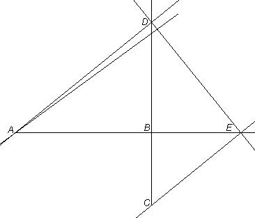
Similarly to the preceding, in the first drawing a ruler for line ADC pivots on A till from B, on arc BD with center A, an arc BC with center D is drawn so that C is also on horizontal BC. Unlike before and in other cases, there is no preexisting radius like DC that could be marked on a ruler, making this a simpler construction than for instance on page 262 of the above book.

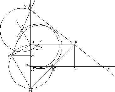
How this construction trisects an angle, here ABC, how for that matter the other drawing leads to a heptagon, will presently be omitted, there being opportunity for these elsewhere. (It may be helpful though to note that in the trisection the angle  DBC is a third of angle ABC, and for the heptagon its initial sides are to be found by, with center H and radius of the circle, marking arcs on it above and below the horizontal—the distance then between the intersections on the circle of either of them and of the horizontal makes a side of the heptagon, with the other sides easily following.) What I wish to include is the following response I received by e-mail from Professor Hartshorne.

From: Robin Hartshorne [mailto:[email protected]]
Sent: Friday, November 15, 2002 6:40 PM
To: [email protected]
Cc: [email protected]
Subject: constructions

 Dear Mr. Vjecsner

Thank you for your letter about constructions. In spite of your protestations, I find nothing controversial in your letter. You have given a mathematically correct construction of the trisection and the heptagon neusis step. These constructions are not classical "ruler and compass constructions" as required in the classical problems, because they make use of the ruler and compass in ways not allowed by the traditional constructions. (See explanation on p. 21 of my book). I would say you have invented a new tool, that is simultaneous use of the ruler and compass in a sliding manner, and with this tool you have solved these problems.

I wonder if your tool is equivalent to the use of the marked ruler--that is can it solve all and only those problems that can be solved with marked ruler?

Sincerely yours,

Robin Hartshorne

The in this e-mail cited p.21, as I mentioned in my reply, allows that "at any time one may choose a point at random, or [a point] subject to conditions such as that it should lie on a given line or circle", which is what my use of "neusis" or "sliding" consists in. And as I indicated, previous attempts at making any of the constructions with only unmarked ruler and compass were unsuccessful regardless of whether those movements are allowed or not. I am reiterating this to bring to attention that the present solutions mean more than the various ones produced with the aid of additional devices.

If this sounds like boasting, I might lessen the effect by saying that an intention of mine is to bring my capacities to people's awareness, so they will give a listen to other things I offer, which I feel are of benefit. The preceding puzzles, again, are among many others I confronted, and are not included in the book of mine spoken of on the home page. This does not mean I do not like to carry the preceding explorations farther, and I have in fact done so and will try to describe them subsequently.

14 December 2002

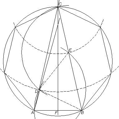
Viewing the first above construction once more, I can add that the pivoting of the ruler, too, can be avoided here, as well as in the other cases. One can start by drawing arcs from B with a center D on arc BD, till a straight line ADC can be drawn with the ruler.

At this point it may be useful to say that the proof of this trisection follows from Euclid's Proposition I.32. By it angle ADB is equal to angles DBC+DCB, which are equal to each other, because triangle DBC is isosceles; hence angle ADB is twice angle DBC, and since triangle ABD is likewise isosceles, angle ABD, also, is twice angle DBC.

In light of such needed complication in even this trisection, probably the simplest compared to those known, which largely depend on the same proposition of Euclid, it may seem implausible if I offer a trisection simpler by far, whose rightness is so obvious that the impulse may be that the process is not legitimate. As to be seen, however, the process is none other than the "insertion" used on the many other constructions. What is more, the only tool for it in this case is a compass.

To trisect angle AOB, with center O draw an arc AB; with a center close to C at estimated third of the angle draw the arc close to AD beginning at A; with reached center close to D at two thirds of the angle draw the arc close to CB beginning at last used center. Then "slide" the compass at C for a more accurate radius till the second arc ends at B.

The job is made still easier than the previous ones by knowing that because thirds are concerned, of the reached difference from the goal of B can be taken an again estimated but much finer third by which the radius is rightly changed, since each small angle must change by that third to attain the correct three angles.

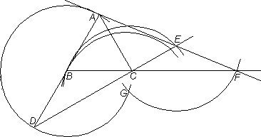
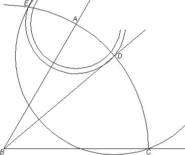
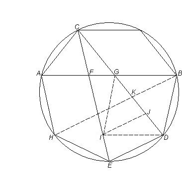
To almost end this session let me return to the heptagon. As was seen, the described construction of it, notwithstanding that the drawing left out parts unrelated to the present issue, is quite elaborate and had to avail itself of insertion regardless, with an added device to boot. Other past attempts, equally requiring insertion and additional tools, were similarly intricate. As the preceding drawing may suggest, however, a much simpler process is possible here, too, as the following drawing will illustrate.

In likeness to the last case, the vertices of the heptagon can be determined by progressive arcs, to end at a specific point. Only 3 arcs are needed; upon estimating the length of a side close to the distance between A and B, draw with center near B an arc from A to a point near C on the circle; with center at that point, draw from A an arc to a point near D on the circle; and with that point as center draw from the point at B an arc toward A to complete the cycle. If that arc ends at A, distance AB becomes a side of the heptagon. As before, of the difference on the circle from that goal of A can be taken an estimated finer seventh, by which the initial radius for BA can be changed, till the third arc ends at A.

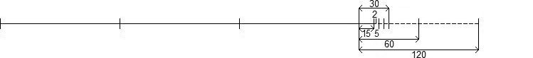
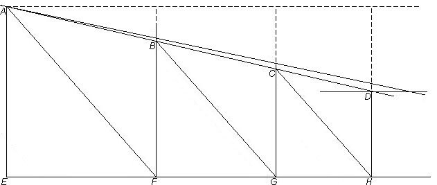
One could, to be sure, keep repeating the first arc, with each successive one centered at the endpoint of the former, till completion. But reducing instead the number of arcs not only shortens the job of "insertion", but the fewer the steps the smaller the chance of physical inaccuracy. The added dashed arcs in the drawing suggest a way to locate the remaining vertices.

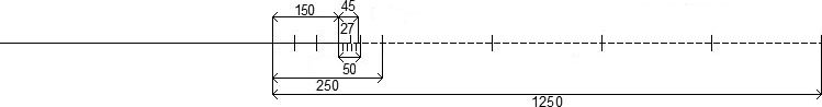
It can be observed that the method in the last two examples can be employed to divide an angle into any number of equal parts, and to construct any regular polygon. The steps can, further, be drastically reduced by the likes of doubling each successive arc as in the preceding. Thus a 100-gon is constructible with 7 arcs.

Estimating the length of its side as radius of the smallest arc in the present drawing, draw the arc from a point A; draw succeeding arcs with centers at preceding endpoints and starting from points shown, until an endpoint near C is reached; and with that point as center, draw an arc from the point at B toward A to complete the cycle. Then, since distance AB amounts to eight times the concerned first radius, take of an eighth of the difference—found by halving the difference 3 times—on the circle from the goal of A an estimated finer hundredth by which to change that radius, till the last arc ends at A. The first radius equals then a side of this polygon. The dashed arc with center A suggests a beginning for correspondingly locating the other vertices.

The viewer should not have too much trouble calculating that the length of the first radius is contained 100 times in the measure starting and ending at A. Counting from A, the first endpoint reached after B can be seen to be 14 times that radius, the next endpoint 27 times, C 54 times, and since B is from C less by 8, namely 46, so is on the opposite side A; and 46+54=100.

Where and to what extent arcs can in this manner be increased (which they needn't be) for a polygon, or for a divided angle, may not be always easy to detect, although there are normally several relations possible for such arcs. My objective was rather, again, to demonstrate that not only can these methods be economical, but that the process of "sliding" or "insertion" can often be performed with simplified structures and compass alone, let alone with an unmarked ruler besides.

It may be added that the above method of constructing any regular polygon or dividing an angle into any number of equal parts is more significant in geometry than it may seem. Geometers may be at a complete loss if asked to construct for example a regular polygon of some arbitrary number of sides. An aid like a protractor may be of assistance, if deficiently so, especially the larger the polygon. The same is the case when approximations for certain polygons exist. In contrast, the above method allows for more precision the larger the polygon, because the relative difference in accuracy can continually be reduced by any practicable amount.

26 December 2002

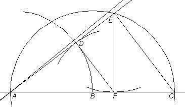
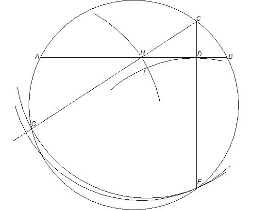
The next drawing utilizes once more the increasing arcs, this time without a need for "insertion", but the drawing is only an expected approximation in regard to "squaring the circle", one of the threesome of ancient problems mentioned. Its aim has been to construct a square of the same area as a circle, a task hindered by the irrational nature of connected pi, the measure of a circle's circumference in relation to the diameter.

In those constructions, pi, which is 3.14159... to infinity, has been approximated to half a dozen and more correct decimal places, and it is not the intention here to trump these, but rather to present a good approximation of exceptionally simple construction, by again only an unmarked ruler and compass. The approximation is to almost five decimal places, 3.14158..., which will be seen to go very far.

Past such approximations relied on rather involved constructions which in the end usually yielded the side of the square of area near that of the circle, and separate from it. One may be at a loss to instead find a construction of the square centered over the circle. From ancient Egypt it may be one that is of some fame, known as of the Rhind Papyrus, and in which the side of the square is 8/9 of the diameter of the circle. Its accuracy as to pi is only somewhere near two decimal places, 3.16..., which nonetheless can in practice be quite adequate. (A substantial reference book on the subject is Pi: A Source Book, published by Springer.) (See a somewhat better approximation with an extremely simple construction on the next page.)

How the Egyptian square was realized appears uncertain, but evidently it was not by use of straightedge and compass. There is such a way, but now to the present drawing. The measurements resulting in its above approximation are 23 units for AB, and 44 for AC, with A and C respectively at half the side and corner of the square, whose intersection with the circle is at B, the point at issue.

Here, too, it may be asked how this can be realized when only the circle is given. The steps used are as follows. With center O of the circle draw prospective diagonals of the square; bisect as shown; on the bisecting line measure off chosen units of 21 (44 minus 23) and 44, at the end of which draw the perpendicular to that bisecting line; with their meeting point as center draw the arc from end of 21 units to that perpendicular; from the point meeting it draw the line to O. At the line's intersection B of the circle and perpendicular to the above bisector draw the side of the square, etc.

The preceding description may sound more difficult than the drawing obviously is, and I think the steps are self-explanatory and need not be justified. I could remark that the counting process, here shown with arcs on the left, is as a rule not depicted in the approximations, with only the resulting structure shown. As noted, further, the measurements are here made by means of increasing and few arcs, with the first chosen bottom radius the unit, and the numbering, which designates distance from center O, should aid in seeing the placement of those arcs.

It remains to give the calculation of the degree of accuracy in this construction as regards pi, known by the Greek letter π. The area of a circle is pi times radius squared, or A = πr2. Therefore A/r2 = π; that is, the area of the above square divided by the square of the circle's radius will yield the approximation to pi. The area of the square is 882 = 7744, and the square of the radius is found by way of the Pythagorean theorem, through the sum of AB squared, 232 = 529, and AO squared, 442 = 1936, for the square of BO, 2465. And 7744/2465 = 3.14158...

If the square roots of pi and of this approximation, 1.772453... and 1.772450... respectively, are considered as sides of corresponding squares, and either of them is divided by the difference, about 0.000003, then 1 mile for either is found to differ from the other by less than 1/8 of an inch.

21 January 2003

9 June 2005

As done elsewhere, I am sandwiching in another item here, of a new approximation that occurred to me of a circle squared. The approximation is fairly good considering that this is the simplest way I found of performing it with unmarked ruler and compass, utilizing the above "sliding" or "insertion" and my circular arcs for division.

 
On a circle with a suitably vertical radius OA (=1) and A as center draw an arc BC such that on drawing with center B arc AD, with center C arc AE, and with center E arc BF, the arc drawn with center F from B meets D. Any part of the circle spanned by radius AB is then 1/13 of the circle, with angle AOB 27.692...°. The cosine of that angle is 0.88545..., and, with a side of the square drawn through B and C, this cosine (=the vertical from O to that side) is half that side. The full side then is 1.7709..., and the square 3.1360..., compared to pi, 3.1415..., the area of the circle (pi times OA² or 1). The difference between that side, 1.7709... again, and the square root of the circle, 1.7724... (the side of the corresponding square), is less than a millimeter for a meter.
 

It may be noted again that the circular arcs I employ to find the ultimate point to be reached are far more accurate than many methods not depending on found points but on predetermined ones, as in various other constructions leading to squares approximating the area of a circle. In those cases, though the steps arrive mathematically at a good approximation, there is no way of checking—by straightedge and compass—that the steps are physically accurate enough. In contrast, the very act of adjusting my arcs for proper "insertion" assures as close an accuracy as physically enabled (mainly the first arc needs adjustment, the others depending on it, which is why I sometimes show it alone drawn twice).

Someone may argue that what is of account in the other cases is their mentioned mathematical reliability, not the physical limitations. However, the methods of "sliding" or "insertion" are equally mathematically correct. As in the preceding, if distances or other requirements are met by the "inserted" elements, then the accuracy at issue pertains. (The paragraph following here and the rest belong to previous matter on this page.)


7 January 2008. I am again squeezing in another item, and the preceding last sentence, in parentheses, refers now to the following matter that starts on a yellow panel. At this time I am depicting an approximation of a "rectified" circle, for an additional method of squaring the circle with straightedge and compass to a fairly good accuracy. The number 3 17/120 yields 3.14166... as an approximation of pi accurate to almost four decimal places, only by one less than the first of the two constructions above and with the present construction simpler by far, at least in comprehension if not in execution.

As should be easy to follow from the image, one way to measure off 3 17/120, after first drawing a line 4 times the length of the circle's diameter, is to continually halve the last of these lengths until 15 units are reached, divide the second 15 by three for 5 units, and then count 2 more fifths for 17/120. The square root of the total (the dashed line discounted), by which to construct the square, is known to be found by a simple method utilizing continued proportion similar to one shown below at right. (In practice, it is only necessary to extend 3 17/120 at left to 4 17/120, use this total length as a diameter for a semicircle, and construct a perpendicular from the start of 3 17/120 to that semicircle. This perpendicular is then the square root sought.)

 
1 February 2008. I am replacing below a former image, because this new one represents a more general approximation of pi as 3.1416, which is better than the preceding 3.14166..., since the 6 alone is much closer to the actual 59... in pi than is the repeating 66.... In fact it is also closer than the 58... in the above first of the four cases depicted. The present approximation is given by 3 177/1250. Accordingly, pictured is the pertinent part of the "rectification" of this pi, similar to the preceding.

As seen, the denominator of the fraction, 1250, standing for the diameter of the circle, or a unit, is the main dimension shown, and above it is measured the numerator, 177, the part of that unit belonging to the length of the pi. Of the 3 units, the whole numbers, that are to precede that part a portion only is shown at left as if a panhandle. Explaining the measuring, 1250 is divided into fifths of 250, the first of which is divided into fifths of 50, with the fourth divided into fifths of 10; from this is obtained 45, divided into fifths of 9, to obtain its multiple 27. This plus the 150 shown then equal the needed 177 out of 1250, the dashed line again signifying the discounted portion.


11 February 2008. I thought of a way to "rectify" approximations of pi, of a circle's circumference, similarly to the preceding two but much easier and as usable for any fractional form of such approximations. Since this page is getting quite cluttered, I am illustrating the method on the next page.
 

So as to treat of each of the triad referred to, a look is here taken at the problem of duplicating the cube. The issue is doubling the volume of a given cube, by again use of only straightedge and compass. Ironically, doing so, by way of “sliding” or “insertion”, was in antiquity virtually accomplished, failing only to put the proverbial “two and two together”.

As described in the book The Ancient Tradition of Geometric Problems by W.R. Knorr, the solution was in different periods attempted both by means of a pivoting ruler similar to the one in the first two drawings here but without recognition that the compass can be of aid (pp.188-9, Dover edition, 1993), and by means of a compass while overlooking the role of a ruler (p.305). Complying with the present drawing (it may be noted that rectangle ABCD is twice as wide as high, the rest to become evident), by the first of these cases a ruler “able to pivot about [B]” would “be manipulated until it assume the position such that [EF] = [EG]”; by the second of the cases, “instead of a sliding ruler [FBG], there is conceived a circle centered at [E] such that the vertex [B] and the two intercepts [F], [G] lie in a straight line”.

It is really the second case where a sliding ruler, other than a pivoting one, can literally be employed. As depicted, the radius of an arc with center E can be adjusted until a line connecting the arc’s endpoints F, G and point B can with a sliding ruler be drawn.

There should be no need now to demonstrate the resulting duplication, the information if of interest obtainable elsewhere. It may be of use though to note that if BC is the edge, viz. the cube root, of the first cube, then CG is the edge of the cube of double the volume.

28 January 2003

6 August 2004

Recently I became aware of another duplication of the cube offered (included on page 270 of the book by Robin Hartshorne referred to on top of this page) which uses a marked ruler. In accordance with the construction below, segment AB makes a right angle with BC, which makes a 30° angle with BD. With distance AB marked on a ruler, it is by "sliding" transferred as distance EF on line AF such that the line lies on A, E is on BC, and F on BD. I again found the following way of achieving this with only an unmarked ruler and compass, as held impossible.

With center B and radius AB draw circle; by "sliding" the compass, find a center G on the circle for a circular arc of radius BG, intersecting BC at a point E, with which as center and radius GE an arc intersects BD at a point F, such that A, E and F lie on a straight line, as determined by the ruler.

The critical first arc is once again shown in two tries, indicating that the appropriate center G must be located. Since the radii are constant, AB and EF are of equal lengths. In this construction, with AB the cube root, edge, of the first cube, AE is to be the cube root of the cube twice the size.

16 September 2004

It should be no surprise if I continue with these constructions, thought to require some device other than compass and unmarked straightedge alone, whether or not performed by way of "sliding" or "insertion", by the indirect way of finding unspecified points through which exact requirements are reached.

For instance, I have been able to so construct with straightedge and compass all forms of cube duplication and angle trisection I have encountered and which often are believed to need involved mechanical devices or geometric shapes ranging from special curves to combinations of solids.

First let me return to a previous cube duplication for which "insertion" is considered used, but the nature of which is not specified. As I noted there, the process can be of greatest simplicity with straightedge and compass alone. One need merely adjust the compass for the radius of the arc until F, B and G lie in a straight line as determined by the straightedge.

Nonetheless, the mentioned book by W. R. Knorr, which contains these, presents also (p.306) a more elaborate version, depicted below first and said to be simpler to execute by "neusis" ("insertion"), without giving an explanation. I am including it here not only because I find it doable with straightedge and compass, though much more involved than the other, but because the result has a certain symmetric beauty.

The idea in this version is that if rectangle ABCD is, with center E, circumscribed by a circle, then upon its intersection of correct line FG at points I and B the segments FI and BG are equal. My way of attaining this with straightedge and compass is as follows. Rotate the straightedge on B so that when with B as center an arc with a radius BG is drawn, and from the midpoint of line FG or its part IB is drawn the perpendicular to meet that arc at a point H, and with H as center and same radius, now HB, is drawn an arc BI, and with I as center and same radius, IH, is drawn an arc HF, the arc will meet line FG at line DA extended. (A much shorter way occurred to me, but I leave the depicted, as perhaps interesting. Rotate line FG on B until a perpendicular through the midpoint of FG or its part IB meets E beneath. The perpendicular is usually drawn in locating that midpoint.)  


The second preceding drawing is likewise for doubling the cube and is accepted as requiring a device like a marked ruler. A somewhat differing form of it is in the above mentioned book by Robin Hartshorne (p.263), but I found the present one more frequent, and it is credited to Newton.

In it an equilateral triangle ABC is constructed; AB is then extended for BD of equal length and line DC is drawn and prolonged, as is done to BC. Thereafter a ruler is marked with distance AB and applied so that one of the marks falls on line DC at a point E, the other mark falls on line BC at a point F, and the ruler goes through A. With AB the edge of the smaller cube, AE is then the edge of the doubled one.

The way I used unmarked ruler and compass instead is by first drawing an arc with center B and radius BA (one could draw a different arc, but this one nicely preserves a circle used to get the equilateral triangle by Euclid's Proposition 1). Then a center G on the arc is found such that with radius GB an arc BE is drawn and with center E an arc GF, with AEF a straight line.

Following further are two depictions of ancient angle trisections, equally included in the book by Robin Hartshorne (pp.262, 269), and that have likewise held to require devices like marked rulers, or curves like the conchoid of Nicomedes (used also for above cube duplications and dealt with in the books by Hartshorne (pp.263-264) and Knorr (pp.219-226). They are similar to an above trisection of mine, which, as noted, is simpler by disposing of the need for marking distances.

First here depicted is a trisection, of angle ABC, attributed to Archimedes. Drawn is semicircle CAE on CB extended; distance AB is then marked on a ruler, which is thereafter so positioned that one of the marks falls on line DC (point D), the other on the semicircle (point E), and the ruler goes through A.

Keeping the arrangement, I dispense with the marked ruler by drawing an arc with a center E so positioned on the semicircle that the arc, drawn from B, meets line DC at a point D that forms a straight line with E and A.


It may have been bothersome to some in antiquity that in that arrangement angle ABC does not contain its sought after third, angle EDB. In any event, the second preceding depiction is of another, similar, trisection that had been given. There seem to have been two basic versions, describable here. In both, to the to be trisected angle ABC is added line AF parallel to BC. In one case, then, a perpendicular is dropped from A to  BC; distance AB is then marked twice successively on a ruler, which is then so positioned that it lies on B, with the first mark on AC (point D) and the last mark on AF (point F); from central mark, E, a line is then drawn to A for elucidation. The result is that angle FBC, contained in angle ABC, is one third of it. In the second case the perpendicular AC is omitted; an arc with center A and radius AB is drawn; distance AB is marked on a ruler, which is positioned then so that the farther mark is on AF (point F), the nearer mark is on arc BE (point E), and the ruler passes through B.

My own solution, without marks, is, on drawing arc BE, position a center E on it for another arc, AF, so that B, E and F are aligned.

Let me in the first following depiction add another trisection, similar to an above one. One difference is that instead of moving the center of the initial arc, its radius alone is adjusted. To trisect angle ABC, with B as center draw arbitrary arc CA; draw with center A an arc DE with a radius of an estimated third of angle ABD, and adjust the radius until with center D an arc CE meets on extended arc CA both arc DE (at E) and line BC (at C).

17 January 2008. This late insertion is about the figure directly below. I felt it would be good to give a simple, non-algebraic, proof of this cube duplication, having to do with observed continued proportionality and also applying to the other cases.

Noting again that in the three triangles ADF, AFE and AEC, AD is to AF as AF is to AE and AE to AC, it follows that with AD length 1, the length (for n x 1 or n) by which AF exceeds AD is the length (for n2) by which AE exceeds AF, and the length (for n3) by which AC exceeds AE. That is to say, AF (n) is the cube root of AC (n3), which, as 2, stands for twice the cube 1, their edges as cube roots respectively AF and AD.


The second preceding drawing returns to cube duplication. I thought it of much interest because it illustrates a basic concept involved, called mean proportionality. In the drawing, for instance, line AE is the mean proportional between AF and AC, because in the right triangles ACE, AEF and AFD, AC is to AE as AE is to AF. It was found that if in a semicircle like the present one the radius AB, namely half the diameter AC, is the edge of the smaller cube, then regarding the same triangles the continued mean proportional AF between AD (=AB) and AE is the edge of the double cube.

Making the construction proved to be a problem, however. The issue is to find point E on the semicircle such that all perpendiculars meet as required (angle AEC is always right by Euclid's Proposition III.31). A famed ancient solution, described in the above book by Knorr (pp.50-54) was given by Archytas, an associate of Plato. He used elaborate intersections of a cylinder, a cone, and a torus, and has been hailed for his ingenuity. Another recent book, Geometry: Our cultural Heritage by Audun Holme (Springer), even utilizes his construction as cover. A much simpler solution should nevertheless be more welcome. The same book also gives a solution (pp.54-55) where two T-squares are used, one of them marking yet distance AD on the crossbar at top from its right inside corner toward the left; that corner is then on arc BD here placed to coincide with a point D, with the other mark on A, the crossbar along a line AE, and the long bar along a line DF; the second T-square has the crossbar at bottom with the inside edge aligned with diameter AC, and the long bar upward. The two T-squares are then so adjusted that the right edge of the long bar of the first meets the left inside corner of the second on AC, while the bottom right edge of the crossbar of the first meets the left edge of the long bar of the second on semicircle AEC.

This would be better visualized with a picture, as in the book, but let me turn to my construction of the same with straightedge and compass. To make it easier to follow the text and picture, I am using the top of the column to the right for the description.

5 October 2004

Presently I felt it of interest to sandwich between earlier items this further consideration of the ancient answer by Archytas to the preceding cube duplication. As noted, the answer availed itself of the intersection of three solids, a cylinder, a torus, and a cone. These were really used only partially, as to be seen. Viewing the drawing below, in correspondence to the last drawn semicircle's diameter and radius as lengths for which mean proportionals are sought the bottom oval below, depicting a circle in three dimensions, has its diameter AB given again as one length, and the chord AC as half that length. The chord is extended to D, meeting line BD, tangent to circle ACB. I may remark that some postulations, like that tangency, are not required. Triangle ABD is to be rotated on axis AB (to describe part of the cone) toward position ABD', for which BD needn't be tangent as said. Also, with arc CEF described by the rotation, line CF is needlessly posited as parallel to BD or at right angles to AB. It will be so by the rotation. To continue, a right cylinder or half of it is constructed on circle ACB, and a vertical semicircle on diameter AB. This semicircle is rotated about A horizontally (to describe part of the torus) toward position AGB', intersecting, like triangle ABD', the cylinder in the process. The same semicircle and triangle will meet on the surface of the cylinder at a point G. Through a series of deductions triangle AGB' is, as above, found to yield the sought after result.

This text comes after the first three paragraphs at left, and is about the construction immediately above. It is done with straightedge and compass by rotating a line AE on A so that on dropping a perpendicular from E to AC, and from meeting point F to AE, the meeting point D falls on arc BD.

I may remark that for these perpendiculars it suffices mathematically to with center E draw an arc tangent to AC, and with center F an arc tangent to AE. But unlike the standard way, after Euclid's Proposition 12 or 11, this is physically not very practical (as is not at all practical the intersecting of three solids as noted at left).

28 August 2008. Regarding the figure directly above, I wrote an explanation above it of how the cube root is determined in it, and not being sure that I made myself clear enough, on the next page I did the like for drawing a square root, maybe helping in the above.


What I want to observe is that this elaborate structure relies like others on "sliding" or "insertion", though it may not be at once evident. The "cone" and "torus" are "loci", signifying the continuous motions of the respective triangle and semicircle by tracing their routes. Accordingly one is by moving them searching for the point, here G, at which they will appropriately meet. In other words, one has to by, as described, rotating both the triangle and semicircle find the point at which they meet on the cylinder. In the drawing preceding this one the point at which instead the semicircle and vertex of the inscribed triangle appropriately meet, is E. As seen, furthermore, the last pictured method is hardly achievable in practice. It is difficult to imagine how the concerned semicircle and triangle are physically rotated so as to meet on the cylinder as required, not to mention a desired solution using only straightedge and compass.

28 September 2004

Possibly more interesting than the construction of double mean proportionality in the last two drawings is the next one. Because of the adjacency of the triangles in their clockwise arrangement, the mean proportionals are easily seen. AB is to BD as BD is to BE and as BE is to BC. A difference is that in the last case the proportionality can continue in principle indefinitely (in the present case this too is possible if supposing overlapping spirals), not necessary for present cube duplication. With AB here twice as long as perpendicular BC, which is the edge of the small cube, BE is the edge of the double cube.

Given ABC, to draw this construction with only straight edge and compass may be viewed as my coup de grâce to the presumed impossibility of the like. The drawing is well known to have been approached since antiquity with a fairly elaborate mechanical device, used in a "sliding" manner of equal involvement. The method is described in the above book by Knorr (pp.57-60) and also in the often referenced books Science awakening by B.L.van der Waerden (pp.163-165) and, especially, History of Greek mathematics (vol.1, pp.255-258) by the most relied on English author in the field, T.L. Heath. He writes:

"If now the inner regular point between the strut KL and the leg FG does not lie on [CB] produced, the machine has to be turned again and the strut moved until the said point does lie on [CB] produced, as [D], care being taken that during the whole of the motion the inner edges of KL and FG pass through [A], [C] respectively and the inner angular point at G moves along [AB] produced.¶That it is possible for the machine to take up the desired position is clear from the figure of Menaechmus, in which [DB], [EB] are the means between [AB] and [CB] and the angles [ADE], [DEC] are right angles, although to get it into the required position is perhaps not quite easy."

Instead, my use of straightedge and compass only, in likewise a "sliding" manner, can be seen to be child's play. Rotate the straightedge on A so that on drawing at meeting point D of CB extended the perpendicular to AD toward AB extended, the perpendicular to DE at meeting point E meets C.


The second preceding drawing is once again a version of a previous cube duplication. It is an admired one by a contemporary of Archimedes, Nicomedes, known also for his invention of the conchoid, a special curve. He used the curve for this construction, and created it with also a mechanical device he built for it. Moreover, the curve had to be specially created for any construction at hand. The mechanical device, the construction, etc., are again found in the books by Heath, van der Waerden, Knorr, or Holme. In their figure, given rectangle ABCD draw line from B through midpoint E of DC to extension of AD at G; from midpoint F of AD draw perpendicular FH of such length that AH equals DE; join GH and draw AI parallel to it; from H draw HIJ meeting AI and DA extended at J so that IJ equals AH (=DE); draw line JBK to meet DC extended in K.

For my construction with straightedge and compass, with center D draw arc EHL for distance DH to get equal AH; on that arc find center L for an arc from D to a point I on AI so that with center I an arc from L meets DA  extended at a point J to make straight line HIJ.

5 September 2007

Again, I am sandwiching in with this text and the next image a cube duplication that will likely be the last one by me, inasmuch as I seemed to have managed to draw with straightedge and compass, using the method of "sliding", all the known variations of the figures (excepting the squaring of the circle) thought impossible to construct with these tools.

The present duplication is a corresponding solution of one that was likewise done with a mechanical device, by Eratosthenes, a contemporary of Archimedes and mentioned previously. He, as also described by T.L. Heath in History of Greek mathematics (vol.1, pp.258-260), built a frame represented here by the top (dashed) and bottom horizontals and the far-left vertical (AE); the horizontal parts had interior grooves in which panes like the leftmost rectangle (which remained fixed) could slide and overlap; the two other rectangles here represent the sliding panes, which were the same as the first but partly hidden; each pane also had the same diagonal (like AF); there was a rod probably attached, to rotate, at A. Now, the edge of the small cube is marked on the last pane as distance DH, which is half of AE; the doubled cube's edge, which is CG, is again found through mean proportionals; to have AE, BF, CG and DH in required continued proportion, the two right panes were made to slide until B and C, the meeting points of the corresponding verticals and diagonals, formed a straight line with A and D.


Here then is my construction of the preceding with straightedge and compass only. With only the solid lines considered, draw lines EH, AE and, at a random distance from the last, BF; draw diagonal AF and auxiliary horizontal at height D. Now rotate a line AD until on drawing a diagonal BG parallel to AF, a vertical GC, and a parallel CH, the vertical from H meets D.

22 October 2004

Let me now return to one of the first problems on this page, the heptagon, drawn for a communication with professor Hartshorne, by whom an e-mail is reproduced. That drawing is about a solution by the sixteenth-century mathematician Viète, and it involves the use of a marked ruler. As was seen, I was able to do the same with an unmarked ruler and also offered a much simpler method, applicable to any regular polygon.

It may be of interest to include more here on the pentagon, in particular a discussion of an answer known as given by Archimedes. It is considered in most of the books cited above, in Van der Waerden (pp.226-7), Knorr (pp.178-182), Hartshorne (p.270), Holme (pp.90-93).

Viewing the first below figure, Archimedes was to observe that in the heptagon if line AB and triangle CDE are drawn, then, with intersections F and G, AG x AF equals GB squared, and FB x FG equals AF squared. On dividing a line AB into these segments then, a heptagon can be constructed. To attain this division, Archimedes, in accord with the second figure below, is said to draw a square ABCD with diagonal AC, and, with AB extended, rotate a straightedge on D for a line DE so that, with intersections F and H, triangles CDF and BEH are equal in area; by dropping the perpendicular FG to AB, the segments AG, GB, and BE correspond to AF, FG, and GB in the previous figure.


To add a comment before proceeding, there is interestingly no indication of how on so sliding the straightedge the equal areas of those triangles are determined. What is more, it appears to me that one could instead similarly adjust in the first figure the three concerned segments until the required areas of the rectangles and squares are attained, dispensing with the second figure. In fact, while I have no knowledge how areas of dissimilar triangles, as in that figure, are with Euclidean tools found equal (in this case, if reversely the segments of AE are known, the triangles can be found), there is a way of finding those segments (of AB in the first figure) by Euclid III.36. If starting with e.g. a segment AF squared, one can find rectangles like FG x FB of the same area, and use "sliding" until GB squared equals in area rectangle AF x AG. (I found later that in the second figure the rectangle formed by the height and base of either triangle in question can be made into a square by Euclid II.14, which then can be tried to be made by preceding III.36 into the like rectangle for the other triangle, having to of course rotate DE again to find the required equal areas in this elaborate process.)

There is, however, an easier way. As noted in Knorr (pp.181-2, 204), the roots of Archimedes' procedure may be compared with those of Euclid's pentagon (IV.11), dealing with properties of isosceles triangles. It has been correspondingly known that, as in triangle ABC in the first figure below, the triangles can be divided into adjacent isosceles triangles with accordingly equal sides, here AB, BD, DE, and EC, as also discussed in Hartshorne (pp.266-7) in connection with the above heptagon by Viète. Now, I want to demonstrate how presently, too, I use only straightedge and compass to construct the triangle and with it the heptagon.


At the midpoint of chosen line AB for a side of the heptagon erect perpendicular FC; with B as center draw circular arc AD; rotate on A a line AC through a point D on arc AD toward FC so that, on completing from the meeting point on FC a triangle ABC, if with D as center an arc BE is drawn, then with center E on the right side of that triangle an arc DC will meet its vertex. (Dashed transversals BD and DE are not required for the construction. They were merely used here for preceding information.)

Triangle ABC can then be circumscribed with a circle (Euclid IV.5), and the dashed arcs with center C and through E and D suggest a way to complete the heptagon. It can also be completed without the circle, with an arc from B centered at A and meeting the lower dashed line at left, and so forth.


The next figure, above, replicates the first one in the preceding pair, but for the addition of some dashed lines. It will be recalled that a special relationship of areas had to be found regarding the segments of line AB for their length. Those lengths, were they still needed for the purpose, are given by the figure at left, without search for the areas. In it AD, BE, and EC correspond above respectively to FG, AG, and GB. To demonstrate, draw HB; then line AFGB is duplicated in DKGC; let triangle EDB in the figure at left be replicated above by GID, for parallelogram GIDB since the sides are of equal length (note the parallelogram above it for length CG and GB); draw IJ parallel to HB and ED. Then IE = JD = KG = FG, and of course DG = AG and CG = GB.

     
26 October 2007. This is again squeezing in an item, after the text following on the yellow panel. At the start of that text I mentioned solutions to well-known problems with some constructions by straightedge and compass. Less known is similar use of those tools for other purposes. Archimedes used for such "neusis", an indirect connection of points, further aids on preliminary constructions in his work On Spirals. Here I am showing one of these as related to that treated in T.L. Heath's A History of Greek Mathematics, Vol. II,  pp.386-8. He speaks of the use of special curves, taking it that straightedge and compass fail (Archimedes may have used a marked ruler, as above). One can, however, again do the job without the aids, as I describe below the diagram at left.
   
It is stated, "Given a circle, a chord [AB] in it less than the diameter, and a point [C] on the circle the perpendicular from which to [AB] cuts [AB] in a point [D] such that [AD is greater than DB] and meets the circle again in [E], it is possible to draw...a straight line [CHG] cutting [AB] in [H] and the circle in [G] in such a way that [HG is] equal to [DE]."

My use of straightedge and compass only is as follows. On drawing the circle and perpendiculars AB and CDE, with E as center draw arc FD, and with an F on it as center draw an arc EG such that with G as center for arc FH, GHC make a straight line.


31 October 2007. It seems I never stop adding to these pages. "Neusis", the indirect connections on this page, was also employed by Apollonius of Perga, regarded as second to Archimedes among the great Greek geometers, and he in fact wrote two books, now lost, on the subject. Their content was described in later work, likewise dealt with by Heath in the volume mentioned in the preceding. On pages 190-2 he speaks about a "construction by Apollonius [that] can be restored with certainty". It contains a rhombus (a parallelogram with four equal sides, like a square), here depicted as ABCD. The object of this "neusis" is that given a length EF, a straight line DHI be drawn such that segment HI from BC to AB extended equal EF.

(5 November. I am indicating in parentheses here the complex way this "neusis" was to be accomplished. The diagonal DB, not shown here, was extended upward to locate a line of the same ratio to EF as AB is to DB, the diagonal; for that line, its square had to equal a rectangle formed by that diagonal extended to a point and the distance from that point to B; "then with [that point] as centre and radius equal to [the line sought, drawn is] a circle cutting [AB] produced in [I] and [BC] in [H]. [HI] is then equal to [EF] and...verges towards [D]". I may note that this equality, etc., may have as well been reached by the known method utilizing marking of a ruler.)

I show now how the neusis can again be simply performed by straightedge and compass. With E as center draw arc FG, and with a G on that arc as center draw an arc EH such that with H as center for arc GI, DHI make a straight line.


My preceding solutions to trisection, cube duplication, and the heptagon, by using only straightedge and compass are difficult for the profession to acknowledge, because of the reluctance to recognize that any of its widely held convictions could be revealed wrong. I consider myself unique in being able to resolve many difficult issues, and therefore the views by many others that a number of general mathematical or scientific claims is false are, although they may instinctively be justified, insufficiently supported and correspondingly dismissed by professionals en masse as coming from the ignorant.

That the above problems could be solved by straightedge and compass alone, even if—in what is called "neusis", "sliding", "insertion", or "verging"—one has to, in order to arrive at the desired construction, find points not given in advance, is, as seen, not held possible, in believing that only the described marked rulers, special curves, mechanical instruments, or other tools can do the task. In the above reproduced e-mail by professor Hartshorne he twice speaks of my method as a tool, in apparent unwillingness to admit that what it consists in is a bypassing of the tools. (14 September 2007. A while ago someone wrote on the web page http://en.wikipedia.org/wiki/Talk:Heptagon, a discussion page for the heptagon entry in Wikipedia, that the heptagon can be constructed with straightedge and compass only, the person giving a link to this page. The discussion continues there, with someone else answering, and me responding. If the reader is interested, I explain there that Euclid did not place a limit on the use of straightedge and compass, such as what points can be connected, unlike contended in trying to prove the concerned constructions impossible, a proof not accomplished otherwise.)

There are in the fields, as I indicated, other assertions—quite a few of them—that I dispute, beside claiming that I can answer many further questions. The preceding is intended to contribute to any confidence I may engender in what I do.

30 November 2004

Some recent findings of mine made me decide to add a little more geometry, but I do it on the next page for which click the succeeding link, my not wanting to overload the present page. To propose to prove Euclid's parallel postulate, the 5th, is ridiculed almost as much as to propose to prove the existence of God. Consequently, if I enter this arena I can only remind the reader that the depictions on this page are in the main of solutions (constructions with only Euclidean tools) not achieved in over 2,000 years by the best of minds. The reader may recognize by this that I am competent and conscientious in my work and therefore do not contend a result lightly. The impossibility alleged of proving the 5th postulate is based on fallacious reasoning I consider elsewhere, and so I encourage the reader to click the following for the next page.

Furthermore, I offer a book review writing service to shed light on my work and its potential impact. If you're intrigued by unconventional perspectives and intellectual challenges, my book might hold interest and benefit for you. Feel free to explore its depths, and be prepared for the unexpected.

MORE ON PRESUMED IMPOSSIBILITIES

To the top and choices