Exploring possible human knowledge


Paul Vjecsner

INVENTION

My interest in intellectual discovery began in my forties with very ordinary things. On seeing that usual methods of securely closing some common containers were troublesome, I found myself able to fairly easily invent better ways. My aim was to, beside solving any of its other problems, utilize the container's material itself, including its required size, dispensing with any additions.

Before the patents below, I received another, No. 3,545,667, which I don't include here because as an early attempt it did not have the utmost simplicity I looked for. The full patents can be viewed at http://www.uspto.gov. (Recently I was informed of another patent searching site, http://www.FreePatentsOnline.com, which may be helpful. If searching by patent number, commas should perhaps be omitted.) It is incumbent on me to say that the period of protection of these patents has expired, my purpose being to, in keeping with the object of this website, present work I did.

14 November 2003

HOME

PRESUMED IMPOSSIBILITIES, continued1, 2

PHOTOGRAPHY, continued1, 2, 3, 4

PORTRAITURE, continued1, 2, 3

COMMERCIAL ART, continued1, 2, 3, 4, 5, 6, 7, 8, 9, 10, 11, 12, 13, 14, 15, 16, 17, 18, 19, 20, 21, 22, 23, 24, 25

INVENTION

AUTOBIOGRAPHY, continued1, 2, 3, 4


This item is described formally in the text of the next image below, belonging to the issued patent. I will try to describe it more informally in this space.

I had initially in mind a lock for the familiar Manila envelope, which has had to add a readily broken metal clasp or a likewise obtrusive winding string.

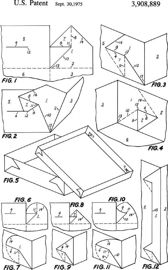
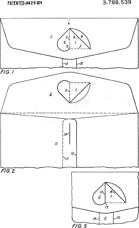
The present lock takes advantage of the glued overlap (12,13)—by which parts of "wall" 11 are joined—to add the vertical slit 10 in which to insert the lock. That lock is located in envelope-flap 3 where it is cut out as shown by the solid lines. Area 9 on top is empty and not strictly needed. What is needed is fold or bend 5—coinciding in locked position with slit 10—an obtuse angle of that fold 5 with the edge of the lock at 7, and fold 2, by which to bend the lock outward.

The significance of these is seen in the figure omitted for some reason at left from my original drawings and added here below the text-page as FIG.3, next to what was instead FIG.4. There FIG.3 shows in three dimensions the insertion of the lock into slit 10 after closing the envelope. Area 11 at the slit merely reveals a cut-out part of the envelope-flap, as it does in FIG.4 (at left FIG.3), which depicts the locked envelope. Now the reason for the low angle at 7, or 15, is that on trying to open the envelope-flap, the motion would be perpendicular to it, for a direction the downward angle at 7, or 15, of the inserted lock will prevent.


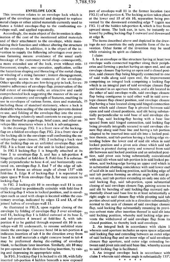
It should be mentioned that the lock can be used on other envelopes that have a closing flap. In cases of stiff material, the above fold 5 may need to be a sharp one, compared to a mere bending in paper envelopes. Slit 10 can for similar reasons be a leftward curving arc, enabling easier access.


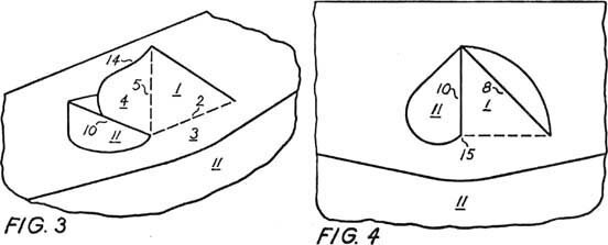
It should perhaps also be said that the lock is swiftly disengaged by flipping it outward at edge 8, in resemblance to its insertion pictured at far left.

Back to first drawings


The next patent is for a corner lock in cardboard boxes, which has been notoriously difficult to invent as a device both simple and firm, and the lock is usable virtually without limit to size and convenience. Of the patent is pictured below only the page of drawings, the descriptive text taking up two pages. I was besides granted the further below reproduced article in the September 1974 issue of Paperboard Packaging, which describes the item along with another one. Additional comments below right.


These drawings depict at the bottom different versions of, beside other parts, tab 7, whose essential attribute is (as seen in FIG.1) that it at point 11 form an acute angle—here 45°—with edge 10. As a result (see FIG.2), after tab 7 is by bending it inward at line 8—to widen that angle—inserted into slit 4, it will not slip out again. In order that edge 10, representing the radius, rotate at point 13, together with wall 3, it must form an angle with edge 9 of at least 90°, the tangent to the arc made by point 11, any smaller angle, like the present 45° one, falling inside the arc, to prevent movement.

It will be noticed (as in FIG.3) that the height of the container need by the whole of locking unit 1, as well as slit 4, be divided into no more than half, allowing usage in very shallow units, like lids (FIG.5). In addition, the downward turned tabs 7 in the interior (FIGS.4,5) prevent obstruction, as when applying the lid, or filling the box.

I should also mention that the bending of tab 7 at line 8 (see FIG.2) need, as in envelopes above, not make a sharp fold (fittingly not shown by a dashed or other line in FIG.10). Tab 7 may only moderately be bent inward to be inserted in slit 4. The benefit is that resiliency will substantially straighten it afterward. As shown also in FIG.10, and 11, edge 9 can curve from point 11 outward, for easier access to slit 4.

This article was first given to me to write, but the editor while retaining it decided not to name an author, having me mentioned instead in the article.


Figures 5, 6 and 7 at left depict a further lock of mine, which was not patented (unlike said on top of the article). I think it to be though ingeniously simple, forgoing modesty here. The lock amounts to an inconspicuous insertion of a tab into a slit, whereafter the two cardboard—or other—panels will no longer separate, because the slits at the ends of the tab allow the receiving slit to partly snap back to its former state, securing the tab. A container can accordingly be sealed without other fasteners.


To the top and choices