Exploring possible human knowledge


Paul Vjecsner

PRESUMED IMPOSSIBILITIES

(continued1)

30 November 2004

As noted on the last page, I am adding to the top of the present one this material on Euclid's 5th postulate. I mentioned the alleged impossibility of proving it and that this is based on fallacious reasoning. How so I go into thoroughly in my book and prefer not to be sidetracked by at this time. I want my book understandably to be read anyhow, because of what I claim is its abundant and significant other content as well, beside including the present explorations.

What I am about to offer is, of course, considered preposterous in its claim, and it regardless consists of not only one demonstration of the 5th postulate, but also of two further ones that came to me later, each of them rather simple. In connection with these demonstrations I will refer to some other authors' work, to perhaps make the ideas clearer.

HOME

PRESUMED IMPOSSIBILITIES, continued1, 2

PHOTOGRAPHY, continued1, 2, 3, 4

PORTRAITURE, continued1, 2, 3

COMMERCIAL ART, continued1, 2, 3, 4, 5, 6, 7, 8, 9, 10, 11, 12, 13, 14, 15, 16, 17, 18, 19, 20, 21, 22, 23, 24, 25

INVENTION

AUTOBIOGRAPHY, continued1, 2, 3, 4


In the above figure the solid lines represent the 5th postulate, which, simply told, asserts that if any three straight lines intersect to form angles a and b that make together less than two right angles then the two upward lines if indefinitely prolonged meet.

The 17th-century mathematician John Wallis proposed moving the right line leftward to meet the left line for a triangle, and supposing similar triangles in any size, he inferred one for the initial state. The similarity, however, is itself an unproved postulate equivalent to the 5th.

One does better moving that line, after making it (dashed line) intersect the other at left, rightward. It will intersect the other only one point at a time, since the two cannot enclose a space (Euclid I.4 and proof in my book, p.131) or meet along a segment, making the lines of different angles. (It is in fact recognized that the distance between two intersecting straight lines progressively increases.) In consequence, since the lines are infinite, each point of intersection reached on moving the (dashed) line to the right leaves behind a next point, and thus the lines never part, namely they always meet, as was to be proved.

The motion can also be explained via Euclid I.15, by which two intersecting lines have their vertical angles equal. The angle between the two upward lines at left in the figure is the same above their intersection as below it. I.e. the lines will at no point of their intersection pass each other.


The next proof is based on Euclid's Proposition 17, which states the converse of the 5th postulate, though thinkers could not utilize it accordingly. It states "In any triangle two angles taken together in any manner are less than two right angles". To merely infer the converse commits the fallacy of "affirming the consequent". "A implies B" does not imply "B implies A". But else is possible.

Triangles of any size encompass all angles a and b, up to when the sides merge into one line, for two right angles or no angle. That is, triangles include all angles of the discussed postulate. Now, it may be asked whether the distance between a and b can be so large that when they make next to two right angles, the two lines will not meet. The question seems justified if it is assumed that similar triangles, ones that have all angles equal, do not exist. Let us then postulate a small enough triangle (its right side represented by the dashed line above) in which a and b make next to two right angles. The angle at the apex, the smallest next to none, can be duplicated indefinitely if lengthening the left side, for ever larger triangles, and the question is will the distance between a and b, which make likewise next to two right angles before merging into one line, also increase indefinitely. This can be settled by Euclid I.28, by which the equal angles at the apex of the two triangles make their right sides parallel. Namely, they never meet, which, with the triangles growing throughout in least amounts, is to say the distance between a and b will increase indefinitely, making the two sides always meet to form a triangle.


The following third demonstration is related to what is known as the "Saccheri quadrilateral", after the logician and priest of the 17th to18th centuries who with it began a lengthy endeavor to prove the 5th postulate and was a precursor of non-Euclidean geometry. He constructed a quadrilateral ABCD like the two below, where all sides are straight and AD and BC are at right angles to AB. (The dashed line, DC, although meant to be straight, is, as frequent, shown curved for illustrative purposes.) Then in conformance with the 5th postulate all four angles should be right angles.

Saccheri embarked on the journey of trying to prove the postulate by showing via reductio ad absurdum that if the postulate is denied, it will lead to a contradiction. He assumed the angles at D and C to be either obtuse or acute (as suggested respectively by the dashed lines), and proceeded to investigate the consequences.

Here I turn to an author who preceded and influenced him, Giordano Vitale. He likewise constructed such a quadrilateral, in order to prove straight line DC to be equidistant from AB, which would again be equivalent to the 5th postulate. He dropped an intermediate perpendicular FE from DC to AB, and attempted to prove this perpendicular equal in length to the others.

This approach, too, can be seen a backward one, as find below.


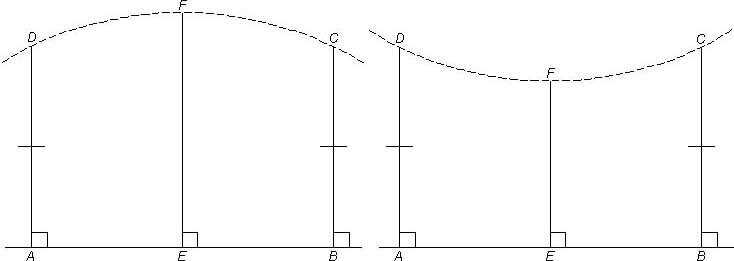
Instead of assuming DC to be straight and trying to determine the length of EF, one can assume EF to be the length of the other verticals and try to determine whether DC is straight. For the answer I will use an unconventional way, by turning from two dimensions to three (consider their non-Euclidean use and an ancient one). The present plane can in three dimensions accordingly be viewed from a side, when appearing as if a straight line. Of interest now is so viewing lines, specifically the above assumed equal verticals and AB. AB would be seen as a point, and the verticals as a single line. (The view is isometric, when size does not change with perspective, as it should not for comparison.) Now because the verticals are of equal height, their upper ends will also coincide in a single point, signifying a straight line. Therefore DC is a straight line equidistant from straight line AB, in equivalence to the 5th postulate. (The corresponding equidistance of parallel lines is a feature implied by the postulate.)

I may add that the three-dimensional way does not somehow violate Euclid, because the issue is to prove the 5th postulate by any method at disposal. Furthermore, as noted, e.g., by T.L. Heath in A Manual of Greek Mathematics, pages 175 or 216, "Plato had defined a straight line as 'that of which the middle covers the ends' (i.e. to an eye placed at one end and looking along the line), and Euclid's 'line which lies evenly with the points on itself' may well be an attempt to express Plato's idea in terms excluding any appeal to sight".


16 May 2005. As time passes, new things occur to me that I feel I want to add to this website, as I've done previously, and this time I am inserting something about the pentagon. Its construction has been seen as one of Euclid's special achievements, because it is based on a great deal of preliminary work by him. It is in fact interesting how beside supplying proofs for his construction, its mere carrying out by him is very elaborate. The reader should not be misled thinking the two pictured below as his; they both are much simpler but again utilize means not Euclidean. Let me indicate the many steps he takes. In IV.11 he shows how to inscribe in a given circle a regular pentagon; for this he first uses intricate IV.10, which in turn uses constructions in II.11, IV.1 and IV.5; of these, II.11 uses I.46, and IV.5 uses I.10; among the last, I.46 uses I.11 and I.31; of these, I.11 uses I.3 which uses I.2, and I.31 uses I.23; the last then uses impressive I.22 which again uses I.3; going back to initial IV.11, it also uses IV.2 and I.9, the first of which uses III.16. The whole then results in the pentagon.


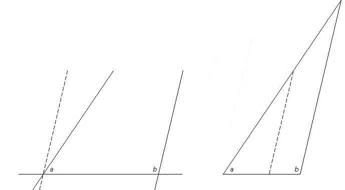
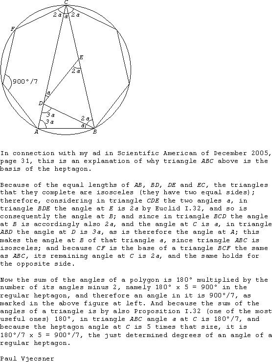
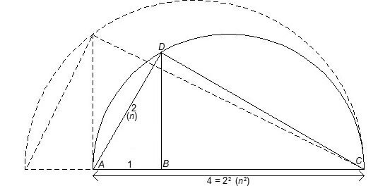
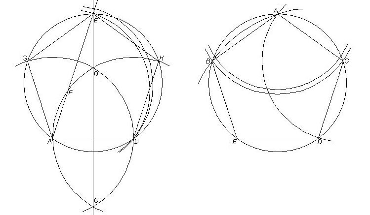
At the start of that construction a triangle with each of two angles double the third angle is inscribed in the circle. The triangle at issue would be the incomplete one below with angles at A, B and E, in resemblance to a preceding heptagon drawing. A pentagon construction like the below has been supposed (e.g. in the book Euclid—The Creation of Mathematics by Benno Artmann) to have been made before Euclid, and it involves a marked ruler, for the here previously discussed "neusis" or "verging". The chosen distance AB is marked on the ruler, which is then so applied that one mark falls on a point E of extended line CD bisecting AB, and the other mark falls on a point F of arc ADH, while the ruler passes through A. The pentagon is then easily completed.

As seen on the preceding page, I have been able to use "verging" with only compass and unmarked ruler in all cases, not held possible without a marked ruler or other additional tool. In the present case, this is possible as follows. On arc ADH find a center F for arc BE such that EFA make a straight line.

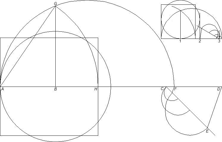
  However, there is yet a much simpler construction also using "verging" or "insertion", as shown on the preceding page regarding, for instance, a heptagon again. Below, on a given circle draw with center A an arc BC such that after drawing with center C arc AD, the arc drawn with center D from A will meet B.

Beside further simplicity, this construction, like the Euclidean one, allows choosing in advance the size of the circle and hence of the pentagon. The construction at left must instead postulate the length of AB and change to the desired size afterward. Correspondingly one has to also either circumscribe the would-be triangle ABE for the circle, or determine vertices G and H otherwise.


Using a simplified construction of the pentagon, rather than the Euclidean one, makes of course a whole lot of difference. The design is used in countless forms to decorate buildings and so forth, as is used the related pentagram (five-pointed star), for example on the U.S. flag and on military vehicles. It may accordingly be of more than mathematical interest that the pentagon, and other regular polygons, can as seen here be drawn by simply utilizing the property of circles to facilitate measurement by using their radii with differing centers.
 
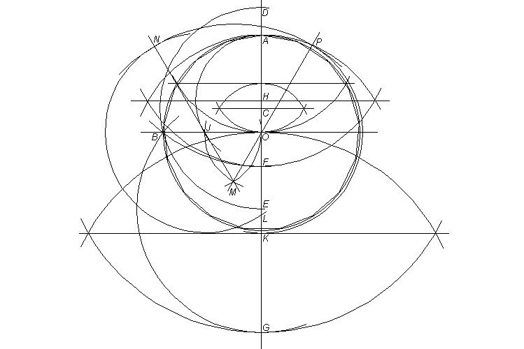
25 May 2005. This time is of interest to me the regular 17-gon, famously found by Gauss to be constructible with only unmarked ruler and compass. Below I drew a version shown in the book by Robin Hartshorne (p.257) and which he called a particularly simple one. To make clear the amount of drawing involved, I in truth added most of the relevant steps that have to be taken. On the circle with center O and extended diameters OA and OB at right angles, get OC equal to 1/4 OA, for which I added the means of twice halving distances; with center C and distance CB draw arc meeting OA at D and E; with center D and distance DB draw arc for F; with center E and distance EB draw arc for G; with center H the midpoint of AF, found as shown again, and with radius HA draw arc for J on OB; with K the midpoint of OG, as shown, draw with center J and radius OK an arc meeting OA in L; to apply that radius here, by Euclid I.2, a point M equidistant from O and J is found, then the extended lines MO and MJ are drawn, whereupon with center O and radius OK arc KP and with center M and radius MP arc PN are drawn, giving wanted radius JN and arc NL. KL is then a side of an inscribed 34-gon.
 
To transfer KL into the circle would require the same Euclidean way just shown (the diameters at right angles require more steps likewise), and of course it has to be transformed into a side of the 17-gon, whereafter, by mainly the repeated use of the compass as measuring device, the entire polygon must be constructed.

But as I showed elsewhere here, the polygons are constructible by such a use of the compass alone, in the indirect way of "insertion", by which the initial radius as side of the polygon is adjusted so that the final required point is met. A big irony is that an above seen method turns out to in practice be more indirect yet, because in the end one has to rely on the physical accuracy of the measuring devices like the compass, and in view of their limitations one has to continually adjust them to reach the required result. Thus with the many many steps in the preceding example there is a corresponding multitude of possible inaccuracies to be adjusted. This possibility is considerably reduced in the more direct use of sides of the polygons as I show on these pages. Moreover, in the above example, and in others—like the preceding heptagon, only a side of the polygon is determined, necessitating the very adjustment for the in the first sentence of this paragraph mentioned "insertion" to meet the final point required.

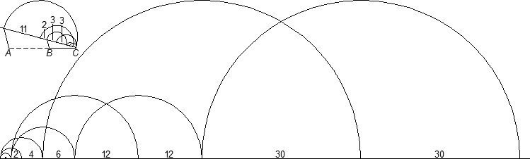
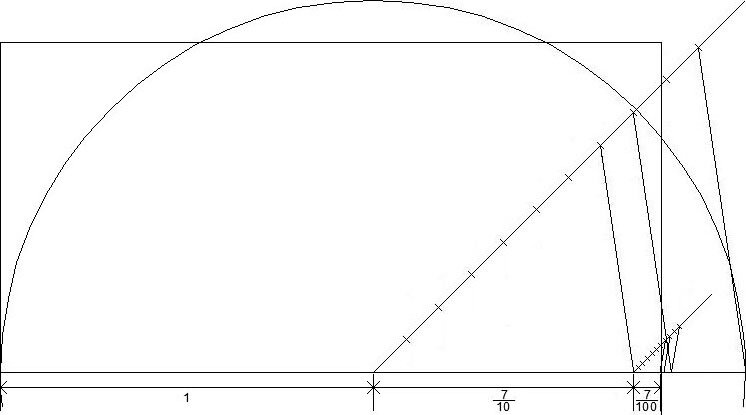
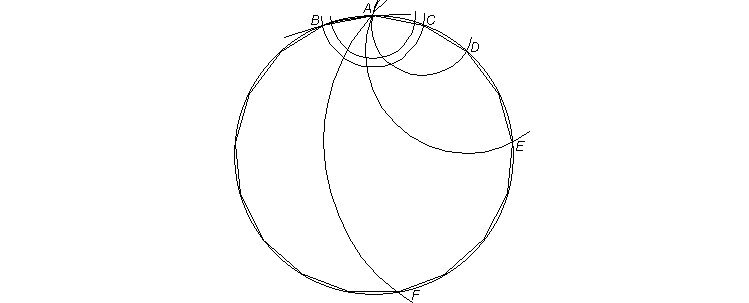
Below is accordingly a simple way I suggest for drawing the 17-gon by requiring only 5 arcs, which bring adjustments down to a minimum. The beginning double arcs on top merely indicate adjustment to the right radius, estimated for the side of the polygon, by with center A first drawing an arc BC; as subsequently easily seen, with center C is then drawn arc AD, then with center D arc AE, with center E arc AF, until with center F the arc through A goes through B.


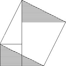
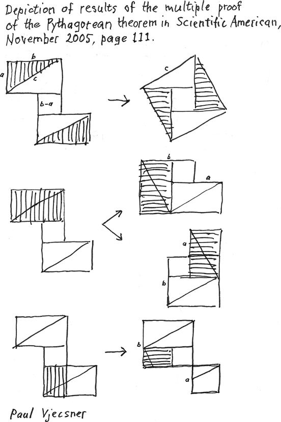
1 November 2005. I decided to squeeze in here another geometric subject, the Pythagorean theorem. As many readers no doubt know, it states that in a right triangle (one with a right angle) the square on the hypotenuse (the longest side) equals (in area} the combined squares on its other sides.

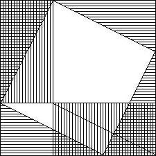
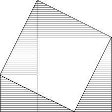
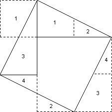
There exist many proofs of the theorem, but there may be less than a handful that are frequently shown, usually ones easily followed. The exception may be Euclid's own proof, at the end of his first book and one of some length and not quite obvious. It is regardless often repeated. Here I am taking a look at a couple of proofs sometimes called proofs without words. They in any event don't require too much comment, and no algebra, which is used for some others.


This proof is customarily shown in two diagrams, and in my habit of seeking simplified answers to everything, I aim for one diagram.

The slanted square is seen as on the hypotenuse, with four of the triangles surrounding it; and the squares at bottom left and top right are seen as on the other sides of the triangle, with the surrounding triangles also four.

A new thought may be to move e.g. the two bottom triangles to the top, rearranging squares.


That arrangement, of the two smaller squares at bottom, occurs on this, another known, diagram, traceable back close to a dozen centuries. The usual proof to me is awkward. Starting by viewing the two bottom squares, the large triangles in them are taken and shown to yield the large square when placed at the top.

But the bottom triangles are much less obvious to fit there than they are at the top, where the proof could start instead, in considering the triangles placed at bottom afterward.


It also occurred to me that showing the whole previous diagram is not needed, it being often easier to visualize something than cluttering a diagram with it.

The present diagram is just an intermediary, to show that by removing one previous shaded triangle it is easy to visualize it replaced by the empty large triangle.


Here in fact I am utilizing this advantage by including two visual proofs in the same diagram. The solid lines obviously depict the previous large square with the two top triangles. It is easily seen that moving those triangles to the opposite sides of that square yields the two smaller squares at bottom.

And if the numbered sections in the large square are moved outside it in accordance with the dashed lines, the smaller squares are seen joined diagonally.


  18 July 2007. At right I am offering another particular depiction of a proof, spurred by one given—at the start of the book The Pythagorean Theorem by Eli Maor—as the simplest known. That proof, however, although graphically economical, is quite difficult to follow, relying on complex geometric understanding. Instead the proof at right hardly requires more special knowledge than that the angles inside a triangle equal two right angles. I added this time letters for the sides, in keeping with the expression of the theorem as a² + b² = c². As easily seen, when the two top triangles inside c² are moved to the bottom as shown, the result is a² + b².    
         
    8 August 2007. I felt I should say more about the proof in the Maor book just discussed. My saying the proof is graphically economical had to do with the basic shape of the solid-line triangles at left, given in the book. That shape doesn't really depict a proof, even with the added squares in dashed lines on a, b and c. The proof must still be verbally explained and relies, as noted, on complex understanding. In Maor's words (p.115), "the areas of similar [alike angles and sides] polygons are in the same ratio to each other as the squares of their corresponding sides". At left, the solid large triangle is similar to the two smaller ones that equal it, and therefore the two smaller squares on corresponding sides equal the corresponding large square. This proof is evidently far more difficult than the preceding one above.  
         

9 December 2005. Still more on the Pythagorean theorem, given as a² + b² = c², is added below. As indicated on top of the sketch, I ran an "ad" in that issue of Scientific American, showing the basic figure depicted three times in the below left column, and informing that the figure, which I called "duckling" (from which flow several proofs, like water flows off a duckling), presents a multiple pictorial proof of the theorem.


This sketch was prepared in response to some inquiries about how the proof is performed.

As seen here, the shaded areas in the left figures are transposed in the right figures, giving c² in the first instance, and a² + b² in the next three.

It may be of interest to note how perplexing the problems were to mathematicians throughout history. The first two figures in the right column here (without the shading) were used in a proof described in the well known book, A History of Mathematics by Florian Cajori (Chelsea Publishing edition, 1991, p.87), and attributed to the 12th-century Hindu mathematician Bhāskara. In it the second of the two figures is (similarly to ones above this sketch) derived from the first, and it is overlooked that in the first figure, while keeping c², its two lower triangles (and their forming the small square) are superfluous for that proof, with the two upper triangles transposed sufficient for the second figure, a² + b².


10 January 2006. As informed by the text under the figure at left, the whole of this addition is also about an ad in Scientific American. The "ad" shows the related construction of a heptagon by use of straightedge and compass, the construction also found on the preceding page here.

The basic reasoning behind the central triangles has been known since antiquity, but I haven't seen it unified in a figure like this, and felt it a good idea to present to any interested reader. I didn't go into all the details (which are easy to look up), like why the angles of a polygon (see e.g. What is Mathematics? by Courant and Robbins, p. 10), and this too is interestingly based on the mentioned Euclid proposition I.32, seen as very fruitful.

   
As noted on the preceding page, I am adding here a much handier method of "rectifying" an approximation of pi, the circumference of a circle, for which task I somewhat rearranged these pages. As indicated, at issue are fractional forms of approximations, and the point now is to easily construct them with straightedge and compass, presently simply as straight lines approximating the length of the circle's circumference. With these lines it then only takes a known brief way to the construction of the required square.

Perhaps the favorite fraction close to pi is 355/113, because of its "prettiness" and accuracy to six decimal places, in 3.1415929.... There have in the past been given constructions of it that bring about some dimension instrumental in attaining the desired square, and they can to an extent be viewed, from ca. pages 240 through 282, in the mentioned Pi: A Source Book. They require, however, variously complicated procedures, which was my intention to avoid.

On the preceding page I showed two rectifications of pi which were done by measuring off on the intended straight lines the fraction approximating it, so as to get the fractional part of the unit considered. The present fraction, 355/113, can be written as 3 16/113, with its fractional part accordingly meant to be placed on a line so as to get 16 parts of 113, the unit. My previous method was to divide that unit as necessary, usually several times, until the needed part of it was obtained.

The difficulty was that the divisions, except for bisections, require each a separate line on which to measure these off, to then transfer them to the primary line, beside the possible difficulty of finding convenient divisions for the particular unit. Now it occurred to me that the entire measurement can be easily done on such a separate line, for a very simple reason. Unlike the line to be fitted, which must be of the diameter of the circle considered, the separate line has no requirement regarding its length. As a result, instead of dividing any of it into certain parts, one merely has to repeat those parts. Below then is illustrated the present case.


The unit, equal to the circle's diameter and to have 113 parts, is given by AC. From C is here then drawn an oblique line of indeterminate length on which the parts are measured off. (In this depiction AC is drawn after the measuring, since, started at the left end, the right end is not known. This sequence is here spatially fitting, but the measuring line can instead be connected at A, with AC already in place.) It should then not be hard to follow the process, seeing that the arcs on top of the oblique line determine the 16 parts, and on the bottom the 113. Connecting the beginning then with a line to A, and a parallel to that line at 16 for B, the proportions are transferred to AC. AB is the fractional part of 3 16/113, with the BC segment again discounted by dashed lines, the 3 to-be-added units indicated to the left of A.
 

As seen, I utilized increasing radii for the arcs as before, to make the process shorter, and more accurate because of fewer steps. The process can be applied to any fraction nevertheless, since one can repeat smaller arcs as often as required  to reach the appropriate numbers.

7 March 2008.

Below I am adding yet another rectification of the circle, based on an approximation of pi by the great Ramanujan. The approximation results from (92+192/22)1/4, the last superscript meaning root to the 4th power, and it is 3.141592652..., accurate to eight decimal places, two more than the preceding. Ramanujan made a corresponding construction, seen in the mentioned Pi: A Source Book, pages 254 and 303. The construction is again rather intricate, ending with the observation that the mean proportional between certain resulting line segments is nearly equal to a sixth of the circumference of the given circle. There is also no proof furnished.

The above formula (92+192/22)1/4 can be written as (97 9/22)1/4, with the number inside the parentheses correspondingly rectified as below, after which the approximation of pi is accomplished by in the known manner drawing the square root twice in succession on reaching the concerned lengths.


The measuring off of 97 9/22 is shown here in two parts, because, I'll admit, the line is quite long and in practice may require paper bought at an architects or art supply store.

In the top left corner, AC designates the unit length, for the diameter of the circle to be rectified, the object there being to find its fractional part, 9/22, marked by BC. On the oblique line meeting C, the 9 parts of 22 are measured off as before, now from right to left, with increasing radii for efficiency, some of the distances marked for clarity; the endpoint reached is then again connected to A, with a parallel for B.

The large figure contains the entire measure of 97 9/22, including 1 unit with the fraction, for a whole length of 98; that unit, corresponding to AC in the first figure, is the starting measure at left for the rest, the corresponding dashed AB discounted as in the other cases; again, some distances are marked for clarity. For the resulting length, as noted above, is then drawn the square root twice in a row to obtain the rectified circle.


14 May 2008.

It happens that I thought of an approximation of squaring the circle which is somewhat better than the ancient Egyptian one mentioned on the previous page, but is of utmost simplicity of construction by straightedge and compass not comparable with any other construction I have seen. It could merely be described in words, but I felt I should show a figure, to display the stark simplicity. It is achieved by making the diagonal of the square 2½ times the length of the radius of the circle, for the approximation of 3.125 to pi, 3.141..., the radius being the unit, and pi correspondingly the area of the circle.


To explain, the square of 2.5, the diagonal, is 6.25, which (by the Pythagorean theorem) is twice the square of a side of the depicted square; half of 6.25 is 3.125, of which the square root, namely the side of our square, is 1.767..., in comparison to the square root of pi, 1.772...; the difference is .0046..., e.g. for a foot it is almost exactly 1/32 of an inch.

The construction is of course quite easy. For instance, one may draw the horizontal and vertical diameters of the circle and then a bisecting diagonal of the required length.


28 August 2008

On the preceding page I illustrated the concept of continued proportionality, when in a figure the ratio of one side to another is continued in an adjacent figure. That illustration had to do with the ancient problem of doubling the cube, which concerns finding the edge of a cube of twice the volume of a given one. The length of that edge is the cube root of the large cube, leading to it.

I tried there to explain without algebra why the drawing led to finding that cube root, but I may not have been clear enough. Since there is a similar way by which the square root of a line segment has been historically drawn, I felt I should here explain that case, non-algebraically again, for easier comprehension of both.

Drawing that square root is related to my preceding ways of approximately rectifying, making a straight line of, a circle, in order to square it. Once it is rectified, one can avail oneself of the present method of drawing the square root so as to get the square.

Below is the graphic I am using to explain such a drawing, and I should note that I found a more space-saving way (solid lines) than the historical one (dashed lines). I'll describe the basic construction on this yellow panel, and then explain the mentioned proportionalities to the right of the graphic. The diameter of the solid semicircle is the line segment whose square root is to be found; the rectified circle, pi, would here be 3 units-plus long, but I used 4 units for clarity.

In the traditional method that line segment is extended by 1 unit (horizontal dashes), the full length is made the diameter of the large (dashed) semicircle, and a perpendicular (vertical dashes) erected at the start of the extension to meet the semicircle. That perpendicular is then the root sought (the oblique lines will be explained later).

In my reduced method, 1 unit, AB, is taken inward from endpoint A of diameter AC, a vertical BD erected to meet the semicircle, and AD drawn, which is the root looked for.


Explaining, triangles ACD and ABD are similar, of the same angles and proportions of their sides, namely AC is to AD as AD is to AB; AD, n, is n x 1; hence AC is n x n = n²; and the root of n² is of course n, which is of interest. In the example, as 2 is to 1, 2 x 1, so 4 is to 2, i.e. 2 x 2 = 2², and 2 is our root.

In the older form shown with dashed lines, the triangles on opposite sides of the vertical being similar, the vertical is, as said, the square root.


8 October 2008

In the figure below, I am applying the preceding way of constructing the square root of a line segment to a rectified approximation of pi, so as to correspondingly square a circle, with the circle and square also shown. The approximation is a known 3 1/7, or 3.142857 (the decimals infinitely repeating), comparing very nicely to pi, 3.141592..., the difference between their square roots being almost 1/5000, e.g. a little over a foot per mile. Under the figure is its description.

24 October 2008. The small figure below uses minimal relative space for drawing a square of any approximation of pi, in area, to the pi of the given circle, as explained here; the bottom horizontal is the rectified approximation (one of 3 1/7 is shown).


The long horizontal AD is 4 units long, of the last of which, CD, is found a 7th, CF, by means of CE of unspecified length and a parallel to ED for getting F; this makes AF the approximated pi, 3 1/7 (to save more space, without CD, CE may be drawn in an opposite direction, to apply to the 3rd unit of AC, which is then extended to a transferred F for the AF of the pi approximation); its square root is by the preceding found by drawing on it as diameter semicircle AGF, and erecting at the end of first unit AB the perpendicular BG; incline AG is then the square root; now, since the area of a circle with unit radius is pi, its diameter is 2 units, as depicted, and the square on its square root is also pi (or its approximation); and incline AG was seen to be the square root of pi, so that by drawing with A as center a circular arc GH, we have the horizontal AH for a convenient drawing of the square. The like can of course be done with other approximations, by which the length of CF minutely differs.
 

14 January 2011

It occurred to me that instead of seeking an approximation of pi for a circle, of which to then find the square root and construct a square, one can start with an actual square root of pi up to some decimal, and easily depict that square root so as to construct the square. The amount of decimals used is in principle indefinite, limited only by the physical possibility of construction. Below I give the description.


As mentioned, since the area of a circle is pi multiplied by the radius squared, if the radius is made the unit then the area of the circle is pi, and the square root of that area is the square root of pi. Pi, 3.1415926..., has, from its first two decimals on, the square root 1.772..., the root depicted above as measured on the circle's diameter (because of space, only about half of the circle, and of the resulting square, is shown). Since the radius is 1 unit, the left radius shows unit 1 of the root; then on a line diverging from the diameter are marked 10 equal parts of convenient length to determine the first decimal, which is 7 out of 10 of a 2nd unit; the endpoint of the marks is accordingly connected by a line to the end of the diameter, and parallels to that line are drawn for 7 and 8 parts; the 7 parts of course determine the first decimal, and the 8th part is for a subsequent division into 10 of one of 10, into 100 for the second decimal; there the process of finding 7 parts is repeated as shown, with an 8th part added for the next decimal, which is so tiny that it, with the rest of the root, fits inside the next pixel here; accordingly I drew a vertical at that pixel together with the vertical at the starting point to construct the upper half of the square.
 

It is noteworthy that if the above radius is a kilometer long (making the diameter well over a mile) then the divisions into ten need only be done 6 times to reach them for a millimeter. At that stage one can hardly find a pointed instrument that marks a finer division, and for all practical purposes the circle is accurately squared there, the width of the instrument spanning the end of the square root and the line beyond. The like applies whatever the length of the diameter. It should be kept in mind that the ancient idea is to make a construction with physical tools, preferably a bare straightedge and compass, but possibly with marks on a ruler, or a mechanical device with sliding parts, as used for some cube duplications.

Let me bring in some further thoughts regarding infinitesimals. In a famous paradox by Zeno (I discuss it with other paradoxes in my book) swift Achilles never catches up with a tortoise, because he has to before pass an infinity of ever shorter distances. We know though that he does catch up soon, with a finite number of steps. The point is that a finite distance (between the two runners) comes to an end, with ultimately a distance small enough not to be divisible. Pi (or its square root) is such a finite distance (for instance 3.1416 exceeds pi by a minute distance). Accordingly, at some above stage the remaining distance is no longer divisible even in principle, and the end is reached.

PRESUMED IMPOSSIBILITIES CONTINUED

To the top and choices